| Abstract | This paper is intended to be a complete guide to trouble shooting the furnace control system of a Day & Night 396GAW000075. This furnace (and its siblings branded under various other names) is very common. This paper is focused exclusively on the control system.
|
| Disclaimer | This guide is to help you troubleshoot your furnace control system. There is no guarantee expressed or implied. I have not run anything in this guide by a lawyer to plug any loopholes that might give anyone the idea that they might be able to sue. However, if you use this guide and it doesn’t work for you, do not rush to a lawyer looking for some way to hold me accountable. It wouldn’t do much good anyway. I am unemployed (or I would have paid someone else to fix my furnace) and the most you would get out of me is my twenty-five year old, Day & Night 396GAW000075 furnace. If you singe off your beard or if your hair catches on fire call a doctor not a lawyer. If you think that you cannot fix it yourself or if you have any doubts about this troubleshooting guide, call a qualified repair person.
|
| Introduction | My attempt to troubleshoot my broken furnace is a story that rivals any furnace battle that might be implied in that top ten Christmas classic “A Christmas Story.” When a furnace fails, most guys think of the money that can be saved by leaving things alone. Just wear a sweater. If you are an old balding guy like me, you already wear a hat around so if the furnace doesn’t work, you just wear the hat in the house too. When our furnace failed, I tried reasoning with the remaining occupants (my wife and daughter) with little success. I showed them how much money we could save, I told them that the gods wanted us to get serious about global warming and the failed furnace was a sign. Then December came and they claimed that they were too cold to listen (for heavens sake, we live in San Jose CA; it hasn’t really frozen here in nearly twenty years). When relatives called to say they would be coming, Mum wanted a working furnace (I actually didn’t get it fixed before they left, but they were from a snowy place and the house seemed warm to them so it didn’t matter). Anyway, I embarked on a search for the truth about furnace function, but I had little idea about how to troubleshoot the control system.
|
| Furnace Control Subsystem | The control subsystem is composed of the following parts (current part # given):
Note: Prices can vary widely on these parts. I have seen everything from expensive to robbery. Click here for a tale on buying parts that is so absurd that I don't know if I should laugh or cry.
|
| Operation | The furnace has two operating temperatures, cold (up until the pilot flame heats the piggyback thermal swtich on the Pilot Module) and hot (after the piggyback thermal swtich is heated). When the thermostat detects that the temperature has dropped below the themperature setting it will close contacts R and W on the Control Board. This will cause 24V to be fed to the Gas Control Unit (to contact 4) and to the Pilot Module. The piggyback thermal switch on the Pilot Module selects between start up and run mode. In startup (system is cold) the thermal switch loops current from the YELLOW wire to the GREEN wire and to contact 5 on the Gas Control Unit. This will cause the pilot valve to open and the the spark to fire lighting the pilot flame. The pilot flame will heat the piggyback thermal switch and when it is fully heated, the switch opens the contact between the YELLOW wire to the GREEN wire and closes the contact between the YELLOW wire to the WHITE wire and to contact 1 on the Gas Control Unit. This will cause the spark to stop and the main gas valve to open. When the main gas valve opens, the burners fire (note: there may be a flash when the burners fire so stay away from the front of the furnace when the cover is off and the main gas valve opens). The fan is on a time delay ciruit. If this stuff doesn't happen, your furnace is broken. |
| Component Breakdown |
|
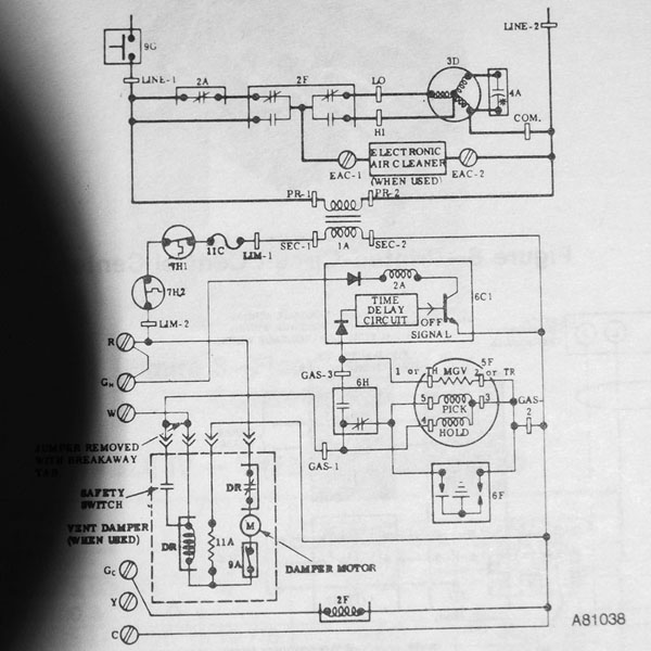
| Schematic Diagram (original) | This is the original image lifted from my furnace manual
|
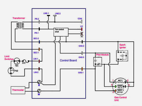
| Schematic Diagram (simplified, with links) | This is a simplified color coded diagram. The Control Board contacts are labled in PURPLE, all components external to the Control Board are labeled in RED.
Click on a component for a photo reference of the part. |
| Tools that you will need |
|
| Troubleshooting (Basic) | Remove covers to the furnace and jumper the contacts R and W on the Control Board (note that there is a power cutoff switch by the Control Board; it is there to cut power when the cover is off). If furnace fires up normally, then you have a broken thermostat. If furnace doesn't fire up nornmally and you get a spark at the Pilot Module, the problem is either the Gas Control Unit or the Pilot Module If there is no spark, you will need more troubleshooting, the order is not specific. However, you probably want to be sure that the main power and the transformer checkout as these are very straightforward. The Limit Switches are also easy to check. I would troubleshoot the Gas Control Unit last. |
| Troubleshooting (Main Power) | Check the voltage on the Controller Board across LINE-1 and LINE-2. If this is not 120V AC, there is no power to the furnace. There are some saftey switches in the main power path, check these.
|
| Troubleshooting (Transformer) | Check the voltage on the Controller Board across SEC-1 and SEC-2. If this is not 24V AC, the transformer is bad. |
| Troubleshooting (Limit Switches) | On the Controller Board, connect a jumper between R and W and between between LIM-1 and LIM-2. If the furnace fires up normally, then one of the Limit Switches is bad. Move the jumper from LIM-1 and LIM-2 to the contacts of the upper Limit Switch, if the furnace works, you have a bad upper Limit Switch. If not, move the jumper to the lower Limit Switch. If the furnace fires up normally, then you have a bad lower Limit Switch. |
| Troubleshooting (Pilot Module) | With the furnace cold (that is no pilot flame), disconnect the molex connector at the Pilot Module. Verify that you have continuity (0 ohms) between the YELLOW wire and the GREEN wire. If the YELLOW and the GREEN wires are open, you have a bad Pilot Module. It is harder to check the hot operation. When the pilot flame heats the piggyback thermal swtich, the unit will open the contact between the YELLOW and the GREEN wires and close the contact between the YELLOW and the WHITE wires. I did this with a test cable that I made. The test cable plugs into the molex (in place of the Pilot Module) so that you can simulate the functions of the piggyback thermal swtich. With the test cable inplace, jumper the GREEN wire and the YELLOW wire, the pilot should light and heat the piggyback thermal switch so that you can check the hot operation or, you could try heating the piggyback thermal switch with a torch (or cigarette lighter). Test for continuity between the YELLOW wire and the WHITE wire.When there is continuity between the YELLOW wire and the WHITE wire, there should be an open ciruit between the YELLOW wire and the GREEN wire. |
| Troubleshooting (Spark Igniter) | With the furnace cold (that is no pilot flame), on the Controller Board, connect a jumper between R and W and between between LIM-1 and LIM-2. Check the voltage at the two input contacts on the Spark Igniter. Stay away from the RED wire, this is high voltage to the Spark Module. If this is 24V, you have a problem in the ignition system (either the Spark Igniter or the Spark Module). You can disconnect the RED wire (do this with the main power to the furnace off), turn on the main power and see if the RED wire arcs to the furnace chassis. If there is no arc, the Spark Igniter is bad. If you don't have 24V at the inputs, check the Pilot Module. |
| Troubleshooting (Control Board) | On the Controller Board, connect a jumper between R and W and between LIM-1 and LIM-2. Check the voltage on the wires at contacts 3 and contact 4 on the Gas Control Unit. If you don't have 24V then check the voltage across GAS-1 and GAS-2. If you don't have 24V, you have a bad Control Board (check the fuse on the board) or a bad transformer. If you do have 24V then the wiring from the Control Board to the Gas Control Unit is bad. |
| Troubleshooting (Gas Control Unit) | If all else fails, you come here. If you are here, you should be sure that the Pilot Module checks out, the Limit Switches check out and the ignition system checks out. On the Controller Board, connect a jumper between R and W and you should be getting a spark at the Pilot Module. If you listen closely, you should hear the hiss of gas feeding the pilot tube to the Pilot Module. If the pilot flame does not light and you have 24V to the Gas Control Module (see Troubleshooting the Control Board) then the unit is bad. For the pilot flame to light, both HOLD (contract 4) and PICK (contact 5) must be raised at the Gas Control Unit. You will notice that the Pilot Module is contected to the Gas Control Unit by the molex connector and when cold, the piggyback thermal swtich will close the YELLOW wire (contact 4) and GREEN wire (contact 5) wires. This opens the pilot valve. If the pilot flame lights and then after the piggyback thermal swtich heats up the pilot flame goes out, this means that the pilot valve is closing when PICK is dropped and that you have a bad Gas Control Unit. After the piggyback thermal swtich heats the main gas valve will open when current is swtiched to the WHITE wire (contact 1). DO NOT POSITION YOURSELF INFRONT OF THE FURNACE WHEN THE MAIN GAS VALVE OPENS, AS THE BURNERS FIRE, THERE MAY BE A FLASH. If the pilot stays on and the main valve does not open, you have a bad Gas Control Unit or a bad Pilot Module. With the pilot flame burning, check the voltage across contacts 1 and 3. If this is 24V you have a bad Gas Control Unit. If this is not 24V then the Pilot Module is bad.
|
| Replacing the Gas Control Unit | If you replace the Gas Control Unit, you probably have to reroute the pilot tube since the old Gas Control Unit has the connection in a vastly different location than the new unit. This is pretty easy, but first disconnect the tube from the Pilot Module. Then carefully reform the tube so that you can route the gas from the Gas Control Unit to the Pilot Module. After routing the tube, connect the tube the Pilot Module (losen the connection at the Gas Control UNIT, remove the Pilot Module, connect the tube to the Pilot Module, carefully tuck the Pilot Module back, screw it down and then tightened the connector at the Gas Control Unit). Replacing the Gas Control Unit also runs the risk of gas leaks. Make sure that you use a suitable sealing product at the appropriate joints (something like the yellow Teflon tape). You can check for leaks by using a mix of liquid soap and water (basically bubble solution). Check all gas connections to the Gas control Unit. |